
Key Takeaways:
- Choosing the right method for inspecting solder joints is crucial for quality control in electronics manufacturing.
- Different inspection methods suit different board designs, from visual checks and AOI to X-ray inspection and functional testing.
- Effective inspection supports PCB assembly quality, reduces rework, and helps meet the appropriate IPC acceptance criteria for the application.
Introduction
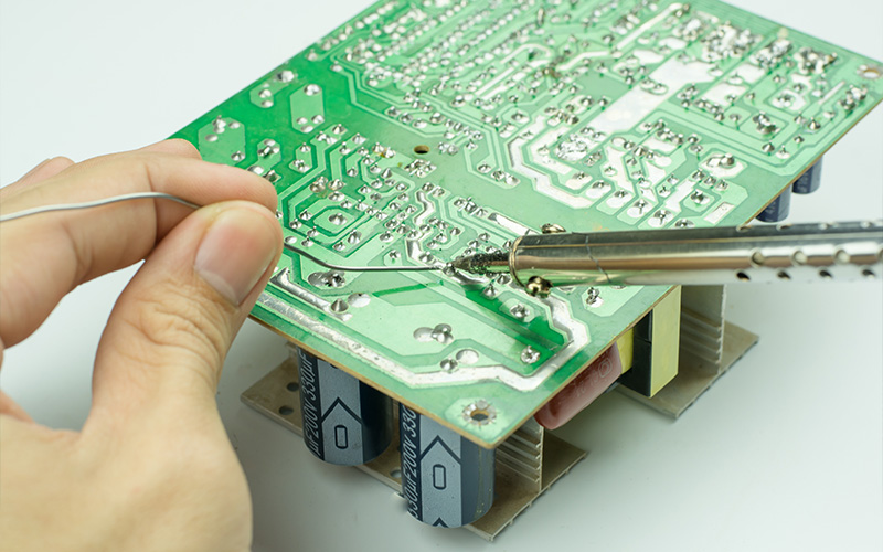
A solder joint is formed when solder bonds a component terminal or lead to a Printed Circuit Board (PCB) pad, creating both a mechanical attachment and an electrical pathway for signals or power. Although small, solder joints are fundamental to overall PCB assembly quality.
Defects such as cracks, insufficient solder, bridging, or poor joint formation can cause intermittent connections, unstable signals, or complete circuit failure. As PCB designs become denser and more compact, inspecting solder joints also becomes more complex. Fine-pitch components, Ball Grid Array (BGA), Quad Flat No-Lead (QFN) packages, and tightly packed layouts can conceal defects, so the choice of inspection method depends on board design, component type, production volume, and reliability requirements.
Why Inspecting Solder Joints Matters
Solder joint inspection is an important part of PCB assembly because even small defects can affect electrical continuity, component stability, and long-term board performance. Effective inspection helps identify problems early and prevent defective boards from progressing further into testing, product integration, or full production.
Confirming Reliable Component Connections
Inspection helps verify that components are securely attached and electrically connected to their pads. Incomplete wetting, lifted leads, insufficient solder, or poorly formed joints may prevent the component from performing consistently even if the board initially powers on.
Identifying Visible and Hidden Defects
Some solder joint defects, such as bridges, excess solder, misaligned leads, or poor wetting, can be identified visually. Others require magnification or imaging, particularly with BGA and QFN packages, where many connection points are hidden beneath the component body.
Reducing Rework and Production Delays
Finding a defect early usually gives the assembly team more options for correction. For prototypes and small production runs, it can also reveal recurring problems before they are repeated across larger batches.
Supporting Long-Term Reliability
Not every defective joint fails immediately. Problems such as voids and cracks may worsen under repeated heating, vibration, or prolonged use. Inspection helps identify weaknesses that may not be obvious during a basic power-on test.
How Inspection Supports IPC Assembly Standards
IPC standards provide recognised workmanship and acceptance criteria for electronic assemblies, helping manufacturers evaluate whether solder joints and component placement meet the required quality level. Inspection requirements also vary by application, with higher-reliability products often requiring stricter acceptance criteria.
Types of Solder Joint Inspection
No single method suits every PCB. Each technique reveals different types of defects and has its own practical strengths.
Visual Inspection
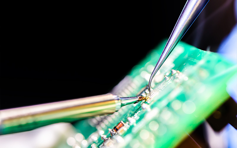
Visual inspection uses the naked eye or magnification to assess exposed solder joints. It can reveal bridges, insufficient solder, poor wetting, lifted leads, component misalignment, and other visible workmanship issues. It remains useful for through-hole parts and components with clearly exposed leads, but it has limitations when joints are hidden.
Automated Optical Inspection
Automated Optical Inspection (AOI) uses cameras and image processing to check component placement and visible solder defects, including missing parts, polarity errors, and misalignment. It works well for repeated SMT production because it provides faster and more consistent inspection than manual checks alone.
X-Ray Inspection
X-ray inspection is valuable when solder joints cannot be seen externally. BGA packages are a common example because the solder balls sit underneath the component. X-ray imaging can help reveal hidden bridges, insufficient solder, voiding, misalignment, and other internal defects. It can also support investigation when a board fails testing, but no visible issue is apparent.
Functional Testing
Functional testing checks whether the completed PCB operates as intended. While the test does not directly show the physical condition of a solder joint, it can reveal intermittent connections, circuit faults, or unstable behaviour linked to soldering issues. For this reason, functional testing is often most useful when combined with physical inspection.
The Importance of Post-Rework Inspection
Rework corrects a known soldering issue, but the repaired area still needs checking before the board moves forward. Heat and manual handling can affect nearby pads, traces, solder mask, or surrounding components, especially in dense layouts.
Post-rework inspection confirms that the new joint is properly formed and that no secondary damage has been introduced. Depending on the component and defect, this may involve visual inspection, magnification, X-ray imaging, or functional testing.
How to Choose the Right Inspection Method
The approach to inspecting solder joints depends on the PCB design, component type, production volume, and reliability requirements. It should target the most likely defects before testing or production.
Consider Board Design and Density
A simple through-hole PCB may allow most joints to be assessed visually, followed by functional testing. Dense SMT designs often need more structured inspection, as smaller parts and tighter spacing make defects harder to identify consistently.
Match the Method to the Component Package
Component type often determines the most suitable inspection method. Exposed leads can usually be checked visually or with AOI, while hidden joints under BGA or QFN packages may require X-ray imaging. Inspection should match the board’s actual component mix.
Consider Production Volume
Prototype inspection focuses on identifying design or assembly issues before the next revision. In larger production runs, inspection must also maintain consistency across multiple boards. AOI supports this by providing repeatable checks of visible assembly conditions.
Consider Reliability Requirements
Higher-reliability products may benefit from more than one inspection technique. Visual checks, AOI, X-ray, and functional testing each reveal different types of issues. Using complementary methods can provide a clearer picture of assembly condition, particularly for boards containing a combination of fine-pitch, hidden-joint, and through-hole components.
Strengthening PCB Assembly Quality Through Better Inspection
Inspecting solder joints is an important part of quality assurance because the appropriate method depends on the board design, component package, production stage, and reliability requirements. Choosing the right combination of visual inspection, AOI, X-ray, and functional testing can help identify defects earlier and reduce unnecessary rework.
MPN Tech supports businesses and manufacturers in Singapore across schematic capture, PCB design, PCB printing services, component sourcing, and local assembly. By reviewing the design and assembly approach early, our team can identify areas that may be difficult to inspect, such as hidden BGA joints, tight QFN layouts, dense fine-pitch regions, or mixed assembly sections. From there, we plan the appropriate inspection method before these issues become production blind spots.
Get in touch to ensure a more coordinated path from PCB prototype to production.

 MPN Tech