
Key Takeaways:
The through-hole assembly process is well suited to components that require stronger mechanical support, such as connectors, relays, and transformers.
Assembly quality also depends on component preparation, placement accuracy, hole and pad design, spacing, solder control, trimming, and inspection.
Manual, machine-assisted, and hybrid assembly each suit different production needs, from single prototypes and R&D builds to higher-volume production requiring greater repeatability.
Introduction
The through-hole assembly process remains an important part of printed circuit board manufacturing, particularly for boards that require strong mechanical connections, larger components, or parts exposed to physical stress. While Surface Mount Technology (SMT) is widely used for compact and high-density electronics, through-hole assembly continues to support industrial systems, power electronics, connectors, switches, and certain prototype builds.
For engineers and businesses, understanding how through-hole assembly works can help set clearer expectations around board design, production time, soldering, inspection, and overall PCB assembly quality. It can also help teams decide when manual, machine-assisted, or hybrid assembly is the most practical option.
What Is Through-Hole Assembly and Why Does It Matter?
Through-hole assembly involves inserting through-hole components into drilled holes in a PCB before soldering them to pads on the opposite side. As the leads pass physically through the board, the resulting joint provides both an electrical connection and strong mechanical support.
It is commonly used for connectors, switches, relays, transformers, and power components exposed to vibration, frequent handling, or higher current loads. While SMT suits compact, high-density designs, through-hole assembly remains useful when durability, mechanical strength, or flexibility for prototypes and small-batch builds is more important.
Key Steps in the Through-Hole Assembly Process
The process involves several carefully controlled stages, from component preparation and placement to soldering, lead trimming, and inspection. Each stage affects how securely the components are positioned and how reliably the finished board performs.
Component Preparation
Before assembly begins, parts are checked against the bill of materials and design requirements. This confirms that the correct values, package types, and quantities are available. The component leads may also need to be checked for length, shape, damage, or oxidation before insertion. Proper preparation helps reduce placement errors and avoid unnecessary rework later.
Component Placement
Components are then inserted into the drilled PCB holes according to their designated positions. Alignment is important because tilted or uneven components can affect soldering quality, mechanical stability, and how the board fits into its final assembly. This is critical for connectors and switches, where precise positioning helps ensure proper mating with enclosures or external components.
Soldering
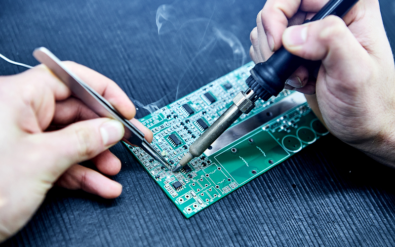
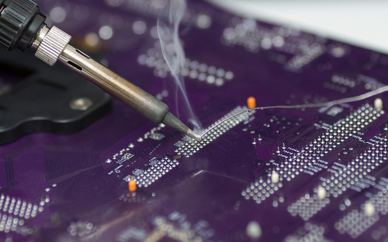
Once positioned, the component leads are soldered to the pads on the opposite side of the PCB using manual, wave, or selective soldering, depending on the board design and production volume. The aim is to form clean, secure joints with sufficient solder coverage to maintain reliable electrical connections and long-term performance.
Lead Trimming and Inspection
Excess leads are trimmed after soldering, where required, to create a cleaner finish and reduce the risk of accidental contact with nearby points. The completed board is then inspected for issues such as insufficient solder, bridging, lifted pads, misaligned components, or incomplete joints before it moves to testing or integration.
Comparing Manual and Machine-Assisted Assembly
Manual through-hole assembly is often suitable for prototypes, engineering builds, and lower-volume production. Technicians can place and solder components individually, which provides flexibility when boards include unusual parts, mixed technologies, or frequent design revisions.
Meanwhile, machine-assisted assembly becomes more useful as production quantities increase. Automated insertion, wave soldering, or selective soldering can improve repeatability and reduce variation between boards.
The right method depends on production volume, component type, board complexity, and cost. For some projects, a combination of manual and automated techniques may offer the best balance between flexibility and efficiency.
Common Challenges in Through-Hole Assembly
The through-hole assembly process can create durable electrical and mechanical connections, but consistent results still depend on careful design and process control. Issues with component alignment, solder quality, hole and pad dimensions, or spacing can slow production, increase rework, and affect the reliability of the finished PCB.
Component Misalignment
Poor component positioning can leave parts tilted, uneven, or improperly seated on the PCB, which may affect both solder joint quality and mechanical stability. This matters for connectors and switches, where accurate alignment is needed to withstand repeated plugging, handling, or physical stress.
Soldering Defects
Insufficient solder, cold joints, excess solder, and bridging can all affect board performance. Controlled soldering conditions and proper inspection help identify these issues before the board reaches the next production stage.
Hole and Pad Design
Hole diameter and pad size must match the component leads to support smooth insertion and proper soldering. A capable PCB board manufacturer in Singapore can help align fabrication and assembly requirements before production begins.
Component Spacing
Through-hole parts usually require more PCB space than surface-mount packages. Sufficient spacing is needed for insertion, soldering, trimming, and inspection, especially on boards that combine multiple assembly technologies.
How Hybrid Assembly Supports Modern PCB Projects
Many modern boards combine through-hole parts with SMT components. Hybrid assembly allows engineers to use surface-mount packages for compact, high-density sections while reserving through-hole mounting for components that benefit from stronger mechanical support.
This approach is common in industrial controls, power electronics, precision equipment, and other boards that need both compact circuitry and robust connection points. For projects that require design corrections or assembly modifications, local PCB rework capability can also help teams resolve issues without restarting an entire production run.
Reliable PCB Assembly Support for Complex Board Designs
Understanding the through-hole assembly process before production helps businesses make better decisions around component selection, board layout, soldering, and inspection. It can also reveal potential assembly issues early, reduce unnecessary rework, and ensure the chosen manufacturing approach suits the board’s complexity, production volume, and performance needs.
MPN Tech Assembly supports PCB projects in Singapore from single prototypes through to full production, with no minimum order quantity for teams that need flexibility during R&D, NPI, or early-stage validation. Our local operations also enable faster coordination when design files need clarification, component substitutions need review, or production requirements change.
Our capabilities include manual, machine, and hybrid assembly, along with support for BGA, QFN, fine-pitch components, and IPC Class I, II, and III assembly requirements. As part of our electronic manufacturing services, we coordinate fabrication and assembly end-to-end to strengthen quality control and support smoother production scaling.
Contact us to find an approach that fits your design, volume, and production goals.

 MPN Tech