

Key Takeaways:
PCB routing is crucial for ensuring efficient electrical connections between components on a circuit board.
Trace width, spacing, pad clearance, and via placement can affect fabrication, soldering, inspection, and rework.
Well-planned routing helps reduce unnecessary path length, electrical interference, and avoidable design changes before production.
Introduction
Printed Circuit Board (PCB) routing is a key stage of circuit board design because it determines how electrical signals and power travel between components. It involves planning the copper traces that connect each part of the circuit while considering factors such as trace width, spacing, route length, via placement, and power or ground paths.
These routing decisions can influence electrical performance, manufacturability, assembly quality, and the overall reliability of the finished board. Their impact becomes more significant in compact, high-density, or fine-pitch designs, where limited space leaves less room for routing errors, clearance issues, or unnecessary signal paths.
How PCB Routing Affects Fabrication and Assembly
The process lays out copper traces across a printed circuit board to create the electrical paths between components. These paths must support the intended electrical function while also fitting within practical fabrication and assembly limits.
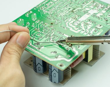
Routing affects fabrication when the layout pushes beyond practical process limits. Features that are too closely packed may be harder to etch consistently, while limited clearance around pads, drills, or copper features can reduce manufacturing margin. During assembly, the same circuit board layout may also restrict soldering, inspection, or rework access.
How Traces Connect Components on a Circuit Board
Copper traces create the electrical paths between resistors, capacitors, integrated circuits, sensors, connectors, power devices, and other parts. Each trace carries a signal or current between the required component connections.
How these traces are arranged can influence overall board behaviour. Direct and logical routes can reduce unnecessary path length and make the layout easier to understand and manufacture. In contrast, poorly planned routes may introduce extra resistance, unwanted coupling, or electrical interference. The routing stage therefore plays an important role in converting a schematic into a functioning physical board.
Why Trace Width and Spacing Matter
Trace width determines how much current a copper path can carry safely. If a trace is too narrow for the intended load, resistance and heat can increase, which is why power routes often require wider traces than low-current signal paths.
Spacing also affects reliability. Traces placed too close together can increase the risk of fabrication defects, electrical shorts, and crosstalk between adjacent signals. For high-speed or sensitive circuits, width and spacing may influence signal integrity. This means trace and spacing requirements should align with the practical limits of the selected fabrication process.
The Role of Vias in PCB Routing
Vias are plated holes that allow electrical paths to move between PCB layers. They are essential in double-sided and multi-layer boards because not every connection can be completed on a single copper layer.
In high-density layouts, via planning becomes especially important because available board space is limited. Efficient via placement can make routing more compact and easier to manage, while poorly positioned vias may create longer paths, crowd nearby features, or complicate fabrication.

Power and Ground Routing Considerations
Power and ground routing are essential to stable PCB performance. Power traces must carry the required current without excessive voltage drop or heat, while ground paths provide the return route for signals.
If these paths are poorly planned, the board may experience noise, voltage instability, or inconsistent signal behaviour. More complex designs may therefore use dedicated power and ground planes to improve current distribution and signal return paths, particularly in mixed-signal, high-speed, or higher-power circuits.
Routing for High-Density and Fine-Pitch Designs
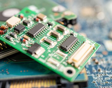
High-density boards present additional routing challenges because more components and electrical connections must fit into a smaller area. Fine-pitch packages such as Ball Grid Array (BGA) and Quad Flat No-lead (QFN) also leave less room for traces, vias, and solder mask clearances.
In these designs, trace width, spacing, layer planning, via placement, and component footprints need to be considered together. A routing decision that saves space in one area may create fabrication or assembly difficulties elsewhere. Working with a reliable PCB design company in Singapore can help identify production risks early. Experts like MPN Tech can review BGA breakout feasibility, via placement, layer planning, and other manufacturability or assembly constraints before fabrication begins.
Common Routing Mistakes to Avoid
Routing mistakes can affect electrical performance, manufacturability, assembly quality, and long-term board reliability. Identifying them early can help reduce rework and production delays.
Using Trace Widths That Are Too Narrow
A narrow trace may not be suitable for the required current. This can lead to heat build-up, voltage drop, or reduced reliability. Power routes should be planned based on the current load they need to carry.
Placing Traces Too Close Together
Insufficient spacing can increase the risk of short circuits, crosstalk, or fabrication problems. This becomes more critical in high-density layouts, where traces and pads are already close together.
Creating Long or Unnecessary Routing Paths
Long trace paths can introduce unwanted resistance, delay, or signal quality issues. Keeping routes as direct as practical helps improve layout clarity and electrical performance.
Poor Via Placement
Too many vias or poorly positioned vias can complicate signal paths and make the board harder to manufacture. Vias should support efficient routing without creating unnecessary complexity.
Weak Power and Ground Layout
Poorly planned power and ground routing can cause noise, unstable signals, or inconsistent circuit behaviour. This is especially important for mixed-signal boards, power circuits, and high-speed designs.
Ignoring Fabrication and Assembly Limits
A PCB layout may look acceptable in design software but still be difficult to manufacture. Trace width, spacing, drill size, solder mask clearance, and component placement should match realistic PCB fabrication and assembly capabilities.
From PCB Routing to Reliable Assembly Support
Effective routing must also survive the transition from Computer-Aided Design (CAD) to production. A design review can reveal issues such as difficult BGA breakout, insufficient manufacturing clearance, poor solder access, or routing that exceeds practical fabrication limits before they lead to prototype rework.
MPN Tech supports routing-focused design reviews by checking how these layout decisions align with fabrication and Surface Mount Technology (SMT) assembly requirements. Our end-to-end assistance across design preparation, prototyping, fabrication, and local assembly helps identify routing issues before they reach production. For businesses developing a PCB prototype project in Singapore, our expertise can also help refine routing around BGA, QFN, compact ICs, and dense layouts during prototype evaluation.
Contact us to review complex routing, fine-pitch layouts, and assembly requirements.

 MPN Tech