

Key Takeaways:
Flex PCB vs Ribbon Cable: Which to Choose
- Flex PCBs offer superior space efficiency for compact designs by reducing bulk, connectors, and cable routing complexity, which supports slimmer and more integrated product layouts.
- Flat or planar cables provide greater flexibility during prototyping and testing, as they are easier to replace or re-route when designs change.
- Flex PCBs are better suited for dynamic applications that involve repeated movement, while flat cables perform reliably in static or mildly flexible environments.
- From a cost perspective, flex PCBs require higher upfront investment, whereas flat cables remain a more economical choice for simpler or short-term design needs
Introduction
When designing compact electronic systems, the choice of interconnect solution has a direct impact on space efficiency, reliability, and long-term performance. Engineers working on modern devices often compare two common options: flexible printed circuit boards (PCBs) and ribbon cables. Both are widely used to manage internal connections in space-constrained designs, but their strengths differ depending on the application context and operating conditions.
This article examines the practical differences between these two components, helping design and hardware teams make informed decisions for compact electronic products.
What are Flex PCBs?
Flexible PCBs, often referred to as flex PCBs, are thin circuit boards built on flexible substrates. Unlike rigid boards, they can bend, fold, or twist to fit around components and inside non-linear enclosures. This makes them well-suited for products with limited or irregular internal space.
Flex PCBs are commonly used in wearables, mobile devices, cameras, and compact medical equipment. Their ability to conform to tight geometries allows designers to reduce overall product thickness and minimise the need for multiple connectors. In many cases, a single flex PCB board can replace several rigid boards and cables, simplifying internal layouts.
What are Ribbon Cables?
These flat cables, sometimes called planar cables or flat cables, are made up of parallel wires arranged in a single plane. They are often used to connect separate PCBs within a device, such as linking a control board to a display or peripheral module. Their parallel wire arrangement supports straightforward routing and termination, which suits designs that depend on direct and uncomplicated point-to-point connections.
From a design perspective, planar cables are cost-effective and relatively simple to install. They are ideal for moderately tight spaces where extreme bending or folding is not required. In manufacturing environments, they are frequently chosen for industrial equipment, consumer electronics prototypes, and systems that may require future modification.
Flex PCBs vs Ribbon Cables: How They Differ
1. Space Efficiency and Design Flexibility
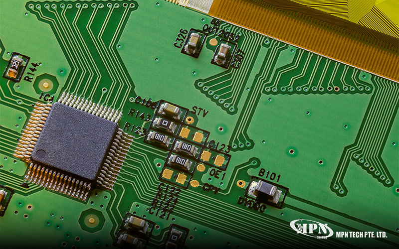
In compact designs, space efficiency is often the deciding factor. Flex PCBs generally save more space than planar cables due to their ultra-thin profile and integrated circuitry. By eliminating bulky connectors and reducing cable slack, they help designers achieve slimmer and more cohesive product layouts.
Planar cables, while flexible, still require connectors at both ends and a defined routing path. This can introduce additional bulk, especially in designs with multiple interconnections. For devices where every millimetre matters, this difference can be significant.
That said, planar cables offer greater flexibility during the design and testing phase. Their ease of replacement makes them practical for early-stage development or systems that may undergo frequent revisions.
2. Durability in Static and Dynamic Applications
Durability requirements vary widely depending on how a device is used. Designed for repeated bending and movement, flex PCBs are suitable for dynamic applications such as foldable phones, hinged devices, and rotating components. Their construction and material selection support reliable performance under long-term mechanical stress.
Flat cables perform best in static or mildly flexible environments. While they can tolerate some movement, repeated bending over time may lead to conductor fatigue or connector wear. For designs that remain largely stationary after assembly, this limitation is usually acceptable.
3. Cost Considerations
Cost is an important factor in any engineering project. Flex PCBs typically involve higher design and manufacturing costs due to specialised materials, tighter tolerances, and more complex fabrication processes. Working with an experienced flex PCB manufacturer can help manage these challenges, but the upfront investment is still higher than for standard cabling solutions.
Flat cables are generally more economical, particularly for simpler designs or temporary setups. They are widely available and do not require custom board fabrication, reducing both cost and lead time.
How to Make the Right Choice for Your Design
There is no single solution that fits all compact electronic designs. Flex PCBs are often selected for high-density, space-critical, and dynamic applications, where reliability and integration are priorities. On the other hand, ribbon cables remain a practical choice for modular, cost-sensitive, or easily serviceable systems.
At MPN Tech, we assess interconnect options early in the development process to ensure alignment with performance, space, and cost requirements. By understanding how each solution behaves in real-world conditions, we help engineers select the interconnect strategy that matches their product goals and manufacturing requirements.
Contact us to learn how we can support your projects.
 MPN Tech