
Key Takeaways:
What You Need to Know About PCB Etching
- Etching is a critical manufacturing step that removes unwanted copper to form precise circuit paths and define final signal routing.
- Wet etching and dry etching are the two main methods, selected based on design complexity, precision needs, and production scale.
- Precision during etching directly affects trace clarity, electrical isolation, and overall board reliability.
- Effective etching depends on accurate design data, precise alignment, controlled etching parameters, and thorough post-etch inspection.
Introduction
Printed circuit boards (PCBs) form the foundation of almost every modern electronic device, from research prototypes to commercial products. Among the many stages involved in producing a functional board, PCB etching is essential in defining performance, reliability, and manufacturability. For engineers, researchers, and product developers, understanding how etching works helps ensure smooth translation from design concept to physical hardware.
This article breaks down the process and highlights the critical steps required to deliver consistent, high-quality outcomes. Keep reading for further insights.
What Is PCB Etching?
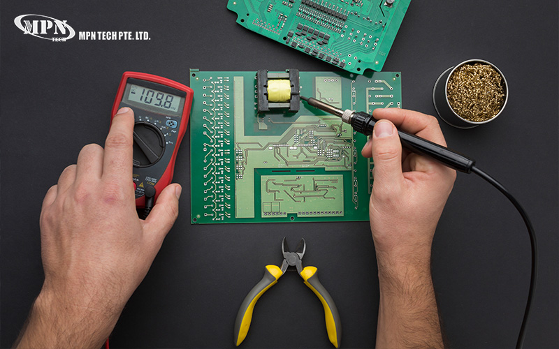
It is a key step in the manufacturing process where unwanted copper is removed from the board, leaving behind only the desired circuit paths. It defines the final layout of copper traces that carry electrical signals across the PCB.
After a circuit design has been transferred onto a copper-clad laminate, etching selectively removes excess copper to isolate circuit connections. The remaining copper traces follow the exact routing defined during the design stage, ensuring that electrical signals flow only where intended.
How It Fits into the Manufacturing Workflow
Before etching begins, the circuit layout is transferred onto the copper surface using photolithography. This process applies a light-sensitive material that protects specific areas of copper while exposing others for removal.
Depending on whether the board layer is internal or external, different materials act as the etch resist:
- For inner layers, photoresist protects the copper traces during etching
- For outer layers, tin plating often serves as the protective barrier
Once the resist is in place, the exposed copper areas are chemically removed, leaving behind clean, well-defined traces that reflect the original design data. This step is critical in both single-layer prototypes and complex multilayer board fabrication.
What are the Two Main Methods of PCB Etching?
There are two main etching methods. The appropriate technique is selected based on factors such as board complexity, scale, and accuracy requirements. Etching must be performed precisely as it can impact trace clarity, electrical isolation, and long-term reliability. Compromised accuracy may result in signal interference, impedance inconsistencies, and reduced yield during assembly or testing.
1. Wet Etching
Wet etching is the most widely used method in both industrial manufacturing and controlled prototyping environments. It uses liquid chemical solutions to dissolve exposed copper from the board. As wet etching is chemically aggressive, precision in timing, temperature, and solution concentration is essential. Over-etching can thin traces, while under-etching can leave copper residues that cause electrical faults.
Common characteristics of wet etching include:
- High throughput for standard PCB designs
- Cost efficiency for small to medium production runs
- Compatibility with fine-line circuitry when properly controlled
2. Dry Etching
Dry etching relies on plasma or reactive gases rather than liquid chemicals. While less common in mainstream PCB manufacturing in Singapore, it is sometimes used for specialised applications requiring extreme precision. For most research, prototyping, and standard production needs, wet etching remains the preferred approach due to its balance of accuracy and efficiency.
Common characteristics of dry etching include:
- Precise control over fine geometries and detailed circuit features
- Reduced undercutting compared to wet etching methods
- Higher equipment requirements and greater process complexity
What are the Key Steps to Ensure Effective PCB Etching?
To achieve reliable outcomes, several key steps must be carefully managed throughout the etching process. When executed correctly, these stages help produce boards that are electrically sound, mechanically stable, and ready for downstream processes.
Step 1: Prepare Accurate Design Data
Design files should account for etching tolerances, ensuring trace widths and spacing remain within acceptable limits after copper removal.
Step 2: Ensure Precise Photolithography Alignment
Proper alignment during photolithography is vital. It ensures that resist layers accurately protect the intended copper areas, preserving the integrity of the circuit layout.
Step 3: Control Etching Parameters
Etching variables such as chemical concentration, exposure time, temperature, and agitation must be closely monitored. The key is to achieve uniform copper removal and prevent over- or under-etching.
Step 4: Conduct Post-Etch Inspection
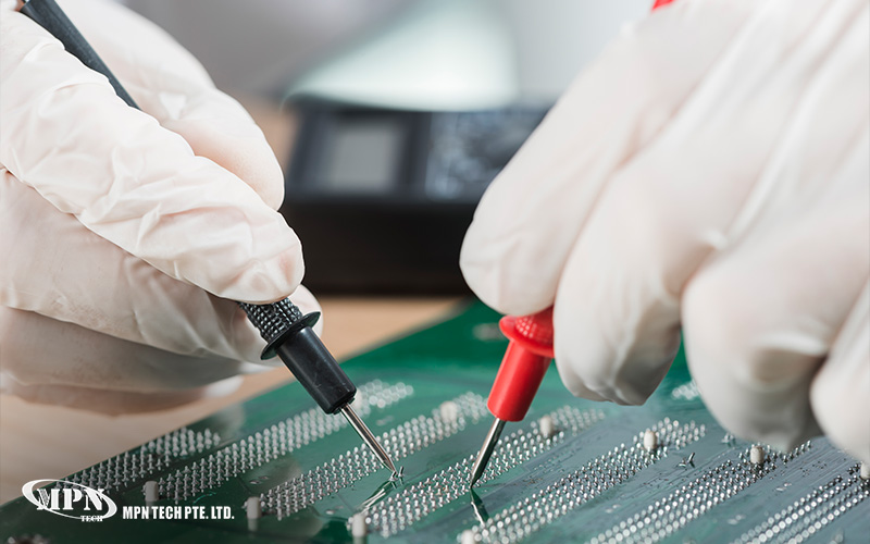
The final step is conducting a thorough inspection. It involves verifying that all traces are cleanly defined, fully isolated, and free from residual copper or defects.
Understanding Etching as Part of the Bigger Picture
While etching is only one stage in circuit board production, it has a disproportionate influence on final board quality. For those involved in prototyping, research, or early-stage product development, understanding how etching works provides valuable insight into design decisions, manufacturability, and supplier evaluation.
At MPN Tech, we provide reliable, fast-turnaround PCB fabrication in Singapore. Our standardised manufacturing and assembly processes follow IPC Class I, II, and III requirements. We are committed to supporting engineers and researchers in achieving consistent, repeatable results across their circuit board projects.
Get in touch to learn how we can support your processes.
 MPN Tech